The detailed procedure below is how to install a modern air
conditioning system into a 1961 Ranchero while maintaining as close
to stock appearance as possible. This Ranchero did not have either
factory or dealer AC installed, just the standard heater box.
The system chosen is a Vintage Air and comes complete with all
parts including modern knobs. However, in this installation, the
knobs will be adapted to work with the original 1961 replacement
knobs.
Warning: This will require drilling holes in the firewall and
radiator surround, as well as removing the heater box and modifying
the hood latch support bracket.
|
Before we start, this is the reference location of the Vintage Air
system under the dash. Note the position in relation to the gas pedal
lever and the glove box area.
|
|
This is a reference of the AC lines in the engine bay.
|
|
AC Box Fitment
|
Trial fit the Vintage Air box under the dash. Note the clearance
on the left and right edges. If the box is too close to the gas pedal,
it will interfere with non-OEM pedal rods.
|
|
At the top of the box, note the clearance to the cowl. Rancheros,
like Mustangs of the same era, have fresh air vents cut into the cowl and
neither was painted from the factory, so they rust out. When
repairing the cowl, delete the fresh air
vents. Or use the supplied block off plate.
The upper mounting plate to connect the box to the cowl bolts to the nut
below the hose fitting (center of image).
|
|
The AC lines exit through the firewall where the blower motor was
originally located. The heater lines exit at the stock location. However,
two mounting holes must be drilled in the firewall (circled in photo). Use
the supplied mounting plate from Vintage Air.
|
|
The three larger holes and two smaller holes must be drilled for the
the mounting bracket on the bottom side of the cowl. There is
approximately 1 1/4" difference between the Ranchero cowl and the Mustang
cowl that needs to be filled. Note the clearance to the wiper transmission
in the upper left corner. We chose to spot weld the bracket in place as we
were doing cowl work and had access. You can use sheet metal screws as
Vintage Air intended.
|
|
This is the small 1 1/4" gap filler bracket. The bracket can either be
screwed to the cowl or welded. We chose to weld it because we had open access
to the cowl. The nuts for the mounting plate bolts were later tack welded to
become capture nuts.
|
|
Use the template supplied by Vintage Air to drill two holes in the
firewall. For aesthics, move the top hole to the center of the strenghening
rib. The bracket will flex enough for this to work. The large holes at the
left edge are the stock outlets for the heater hoses.
|
|
AC Compressor
|
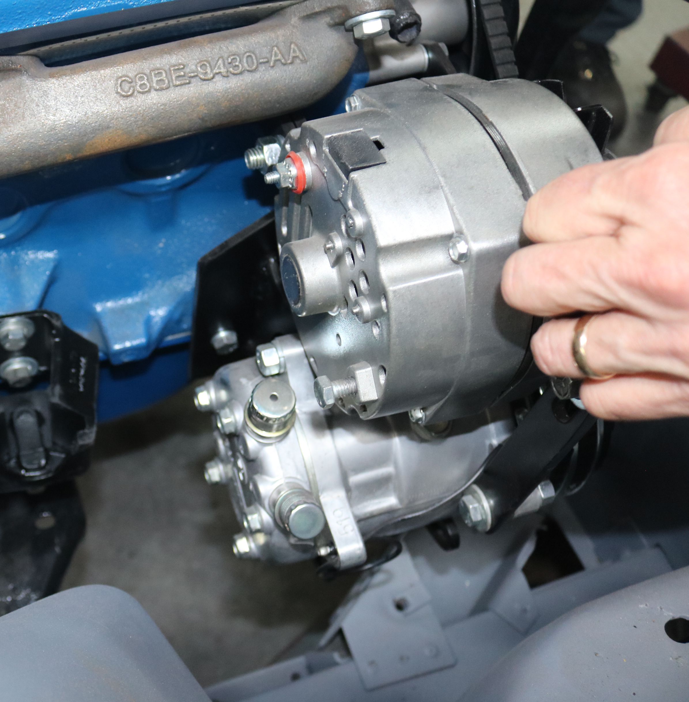
Routing for the dual belt AC compressor. The alternator used here is a GM
style, internally regulated, in a Ford case (1 wire). The OEM generator will not clear
the AC compressor. The original OEM exhaust manifold will clear, but aftermarket
tube headers may not clear. Note that the factory heater hose fitting exits
straight out of the head. A 45 degree fitting will allow the hose to flex
and not rub the altenator.
|
|
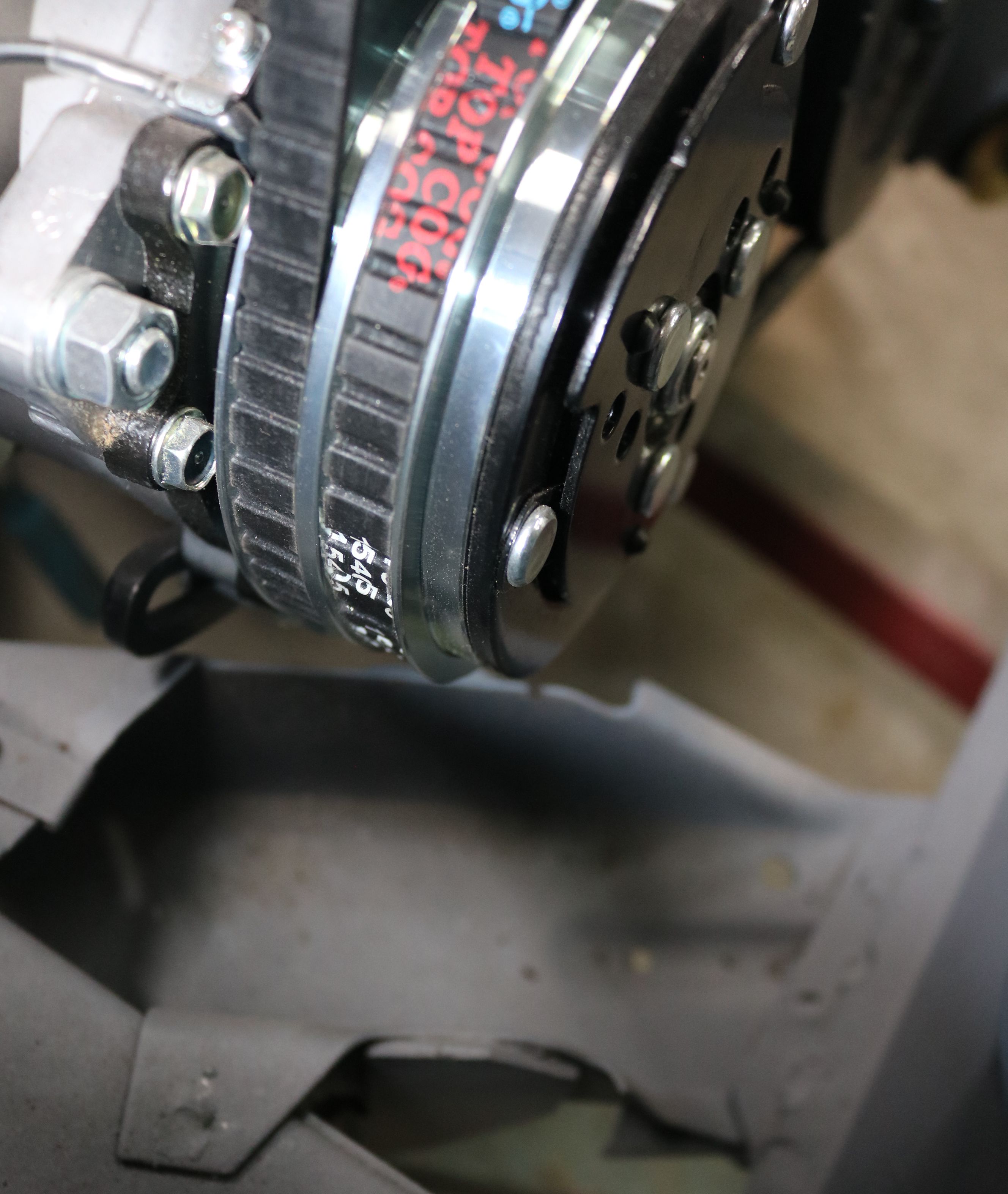
The AC hose outlets on the back of the AC compressor.
|
|
Caution on AC compressor installation. With the straight 6 cylinder engine, the
air conditioning compressor rests on the front strut rod mount. You will also need to
relocate the passenger side horn as it also bolts to the strut rod mount and will
not clear the AC compressor.
|
|
The frame rail was clearanced and should have a new top plate welded on.
|
|
The altenator brackets had to be modified to move the altenator toward the
passenger fender to clear the tube headers, which then left no room for a battery
in the stock location in the engine bay.
|
|
Control Knob Construction
|
Locate an OEM control shaft. If you want to retain a stock appearance on
the dash, this will need to be modified to interface with the new shaft
extension in the Vintage Basic 3 Switch Kit from
Newport Engineering.
|
|
Cut the OEM control shaft off just past the threads.
|
|
The OEM control bezel, with the center shaft removed.
|
|
The OEM bezel from the Choke pull bezel. The other two bezels will need
to be drilled out to the same size.
|
|
Comparison of the two bezels.
|
|
Switch from the Vintage Basic 3 switch kit.
|
|
Shaft extension must be modified for the fan switch to accommodate the mounting
to the dash. This is only necessary for the fan switch.
|
|
Vintage Switch from Newport Engineering shaft mounted. Note the factory bezel
mounting plate (upper left). This is still required to mount the bezels. Next to
the steel wool is the bezel and nut for retaining the fan switch into the dash. The
defroster and temp bezels are male threaded. The fan switch is female threaded. The
matching male half is made into the factory switch, so factory switch will need to
be disassembled to retrieve the threaded portion for reuse. Discard the rest of the
factory switch.
|
|
Mock up of the completed assembly. The large colored washer represents the dash.
|
|
Reuse the threaded portion of the fan switch. You will need to drill out the
two small brass rivets that hold the switch together. Then remove the top of the
switch.
|
|
Remove the large flat washer but keep the nut and the threaded portion.
|
|
Mock up of the fan switch. Note that there is no shaft sticking out for the
knob to attach to. The fan switch nut is too small to accept the larger extension
shaft. The diameter of the shaft in the middle segment will need to be reduced to
the size of the smaller first segment. Since the fan nut cannot be drilled out,
the extension shaft will need to be modified.
|
|
We used a drill as the rotating part of a metal lathe and a file to reduce
the center part of the extension shaft.
|
|
Mock up of the dash with correct placement of the bezels. The
"Pull for Temp" and "Pull for Heat" are not reproduced with
correct markings. The reproduction knobs for the defrost and temp are designed to
thread onto the original cables. These will not work with this Vintage Air system.
The reproduction knob shown is for the fan or wiper switch as it is held in place
with a set screw. All knobs will now turn and NOT pull. Discard knobs in Vintage
Air kit.
|
|
Side view of the dash mounting mock up. The retaining nuts are in place but
the retaining plate for the switches is not.
|
|
This is the template for the retaining plate to reduce the bulk under the dash
and keep the Vintage Air switches from rotating in the dash. Fold at the horizontal
lines and drill out the center of the colored areas.
|
|
Top view of the dash mounting mock up.
|
|
The mock up of the modified bezels and switches installed in the dash.
|
|
To create the installation assembly, the parts were laid out in order, minus the fabricated bracket as it was being painted.
|
|
The completed assembly ready to be installed in the dash. We cleaned up and painted both the mounting plates.
|
|
The completed assembly installed in the painted dash.
|
|
AC Condensor
|
Make a template of where the AC lines will pass thru the core support. The
template supplied by Vintage will not work on the Ranchero.
|
|
Use the template to help locate the line pass thru at core support for the
condenser. Condenser is not in the final location here. Drill a 1 1/4 inch hole
in core support.
|
|
When mounting the condenser ensure there is plenty of clearance on all sides.
Any rubbing will wear a hole in the condenser. I used paint sticks for clearance.
Mustang condenser is 18 wide by 16 tall. The Falcon Ranchero only has room for an
14 tall condenser; be sure to order the 14 condenser from Vintage. Talk to Vintage
Air and they should be able to exchange this in the kit prior to shipping.
|
|
Final location of condenser; note the 1.25 hole in the lower left. When
assembled, this is located under the battery tray.
|
|
The two slotted holes are for the battery tray mount. Note the scuffed paint
in the lower left corner of the core support near the condenser; the core support
must be clearanced to clear the tank of the condenser on both sides. A hammer will
suffice for this.
|
|
I did not like the brackets supplied by Vintage, so I made new ones. Note the
extra space to the left (passenger) side of the condenser to allow the lines to pass
thru.
|
|
The other bracket and space on the right (driver) side. The extra space is not
needed here, so the condenser is mounted off center to allow more space on the
left (passenger) side.
|
|
The bolt in the center of the picture is mounted thru a steel plate in the
bottom of the condenser and will be used to mount the hood latch support bracket.
There is a rubber washer needed here between the condenser and the mounting bracket.
|
|
Final mock up with radiator mounted inside engine bay, behind the condenser.
Note the AC lines off to the left (passenger) side of the radiator.
|
|
This is the 61 OEM hood latch support. The '62 & '63 have a different style
of hood latch. The '60 is similar to the '61, but the grill is different and may
have fitment problems. This bracket had to be modified on the '61 to allow
clearance for the AC condenser.
|
|
The bracket must be flush to the tab (circled). The bracket will need to be
modified at the edge of the yellow tape to fit.
|
|
The top of the hood latch support bracket. The holes in the top plate must align
with the holes in the core support for proper fitment.
|
|
The modified hood latch support in place. Notice that one hole for the hood
latch catch is missing. This will need to be added back in later.
|
|
The hood catch was modified to work properly in it's new location, making it
taller and with more bend.
|
|
One note on final installation - install the AC condensor prior to installing the front valance. There is not enough clearance to slide into place after the valance is bolted on.
|
|
Glove Box
|
The stock glove box will need to be modified to fit as the under dash unit
occupies part of the space. The glove box has an angle to the bottom. If that angle is removed and the back is flattened, it should be a close fit. Note the angle to the back right corner. Trim as necessary. The glove box can be reassembled using pop rivets.
|
|